Capturing Signals and Data
The Active-Pro™ Software runs and displays the captured data from your embedded system. The software comes up in the following state, ready to capture and visualize your data.
Quick Setup Configuration
The ACTIVE-Pro can capture all of the input channels on the ACTIVE-Pro. With a ACTIVE-Pro plugged in, it can capture 8 channels of digital and 3 channels of analog at the same time.
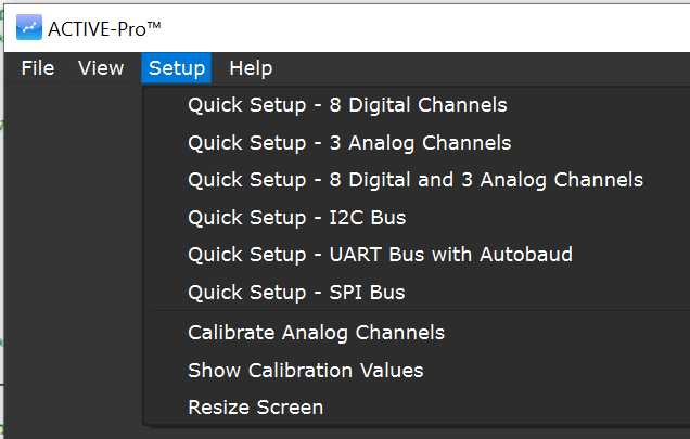
Although you can individually show each signal, there are a number of Quick Configurations that let you instantly select just the channels you need.
To select a configuration, click Setup on the menu and select the Quick Setup configuration of your choice. Below shows the available Quick Setup options for the ACTIVE-Pro.
Selecting Channels to Capture
Select the top tab on the right hand side of the screen to show the Input Channel Setup window.
Analog Input Channels
To enable or disable capturing of an analog channel, click the CH1, CH2, CH3 or CH3/CH4 button. Select the analog input range using the drop down box to choose -10V to +10V, or 0V to 20V ranges. Select the analog sample rate using the drop down box from 10 sps to 1 Msps.
Digital Input Channels
To enable or disable capturing of a digital channel, click the0, 1, 2, 3, 4, 5, 6, or 7 button. These buttons determine if that channel will be captured, and a waveform of the signal will be displayable.
ACTIVE Digital Logic Threshold
The ACTIVE-Pro features variable Digital Logic Thresholds that can range from 0V to +4V. Set the logic threshold to the logic family you are using. This will set the voltage level that indicates the change from a logic “0” to a logic “1”.
If this level is set incorrectly, or too close to either the top or bottom of your logic range, you will see inconsistent waveforms and this level will need to be adjusted.
Hardware Bus Decoders
There can be up to 4 hardware bus decoders that operate on the associated signals. These bus decoders are active even if the digital input signal is not captured. Select the type of bus by clicking the drop down list.
Available Device Capture Types for each device A, B, C and D are:
ACTIVE-PRO Debug Bus
EE101 Debug Bus
I2C, SPI, UART, RS232, 1-Wire, MDIO, LIN, DS101, and CHSI
Helpful Hint: To maximize the performance of the capture, make sure that any channels that are not necessary for a trace are turned off.
UART modes, ACTIVE 1-Wire and EE101 1-wire busses have an Auto Baud feature. When you press the Autobaud button, the Active-Pro measures the digital inputs for 1 second and computes the baud rate of the signals for that device at that time. It then sets the baud rate setting to the value calculated.
Capture
To capture data from your circuit, make sure the Active-Pro™ is connected via USB and press the Capture button. You will see the data being captured scrolling into view.
Once the Capture is in progress you can scroll and view it as it is being captured. Be aware that all of the data is continuously being stored to your disk (in your Users/AppData or Users/Library directory). The total number of captured bytes is displayed at the bottom during capture.
IOnly signals and channels that are used are shown on the display automatically. So if your firmware only outputs data on one channel, only that channel will be shown. This eliminates any setup of the wavelines displayed.
When you have gathered enough data to your liking, you press the same button (now labeled Stop) to terminate the capture.
Pressing Capture again will erase the previous capture and start a new capture.


